Project Overview
This project transforms a standard Proxxon MF70 milling machine into a precision CNC capable of machining cast aluminum parts to tight tolerances. The modifications include implementing full CNC control, adding a 4th rotary axis, extending Y-axis travel from 46mm to 80mm, increasing Z-axis travel from 70mm to 140mm, dramatically reducing backlash across all axes, upgrading to a more powerful spindle motor, and retrofitting the spindle to accept ER11 collets.
The unique constraint: all modifications must be completed without access to another milling machine. My available tools are limited to FDM and resin 3D printers plus a drill press. Additionally, the entire build must remain cost-effective.
Building a CNC from scratch using ball screws and linear rails would exceed both my budget and capabilities. Instead, I'm strategically modifying the existing Proxxon platform with carefully engineered solutions.
Diagnosing Critical Spindle Runout
My first challenge involved the spindle upgrade. After installing a USOVO ER11 spindle adapter, precision measurements with a dial test indicator revealed unacceptable runout on mounted endmills. Systematic investigation identified the internal taper as the culprit, exhibiting an alarming 28µm Total Indicator Reading (TIR). For precision machining, this level of runout makes achieving tight tolerances virtually impossible.
Engineering the Backlash Reduction System
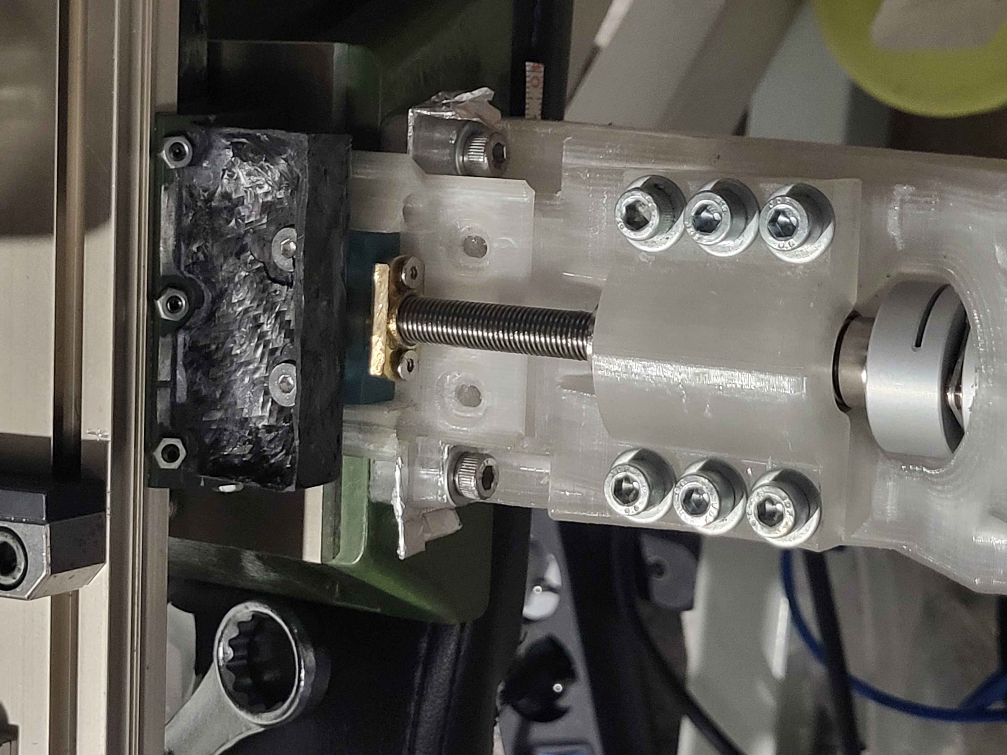
Eliminating backlash required extensive engineering analysis. Using FEA simulations, I validated a hybrid approach: 3D printed PETG motor mounts for precise positioning, reinforced with bonded steel plates to create a steel-plastic composite structure. This design minimizes deformation under cutting loads while remaining manufacturable with available tools.
The system holds NEMA 23 stepper motors and custom bearing blocks supporting T8 ACME leadscrews with anti-backlash nuts. Critical to long-term usability, every component is designed for easy access and maintenance—no need to disassemble the entire machine to adjust a single fastener.
I avoided thrust bearings due to their axial preload requirements. With PETG's susceptibility to creep under sustained loads, thrust bearings would gradually lose preload and introduce backlash over time. Instead, I engineered a dual ball bearing system with a precision spacer, preloaded using lock nuts. The entire bearing block clamps to the motor mount via a shell design that distributes loads across a large contact area, preventing localized deformation.
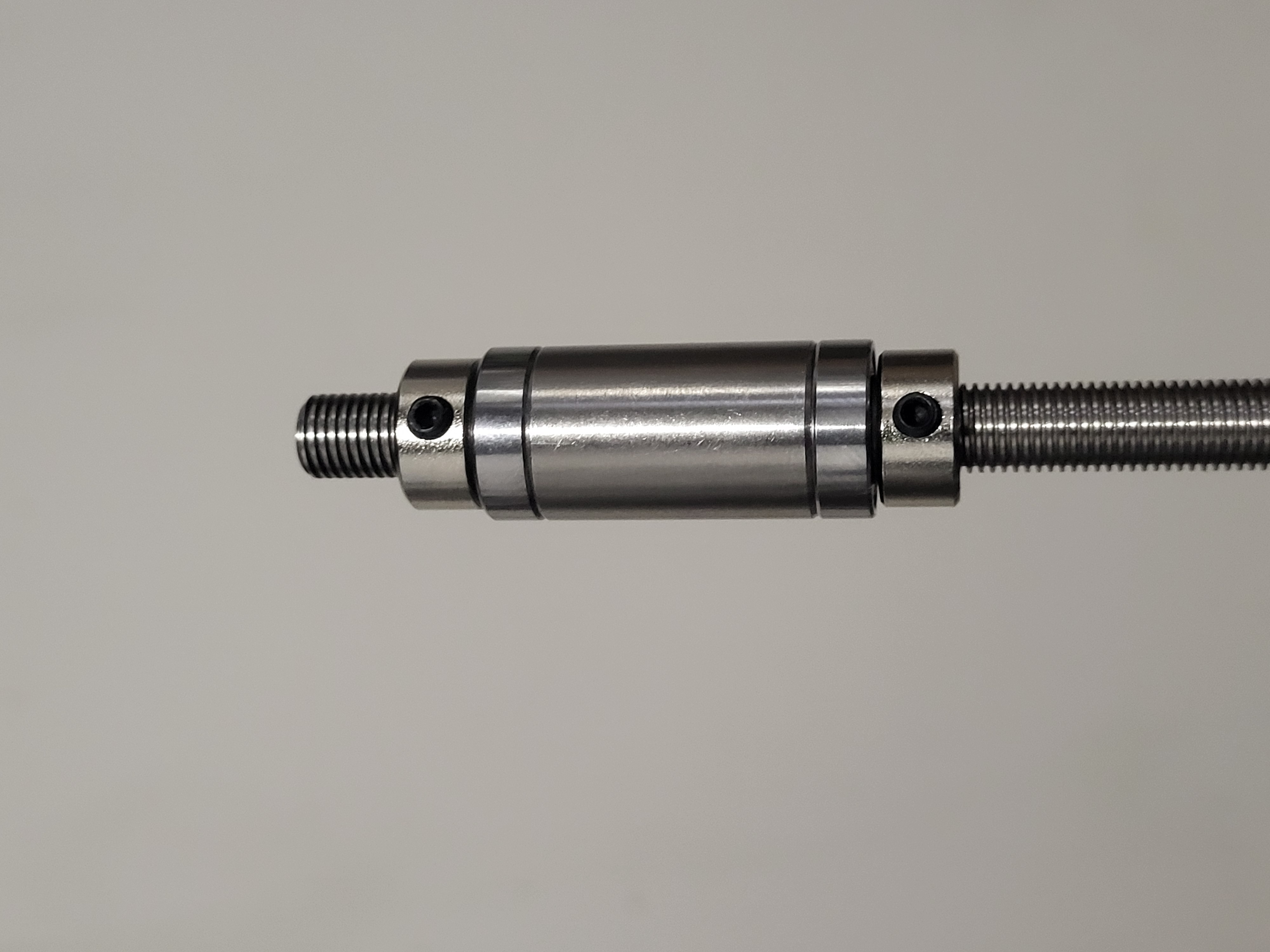
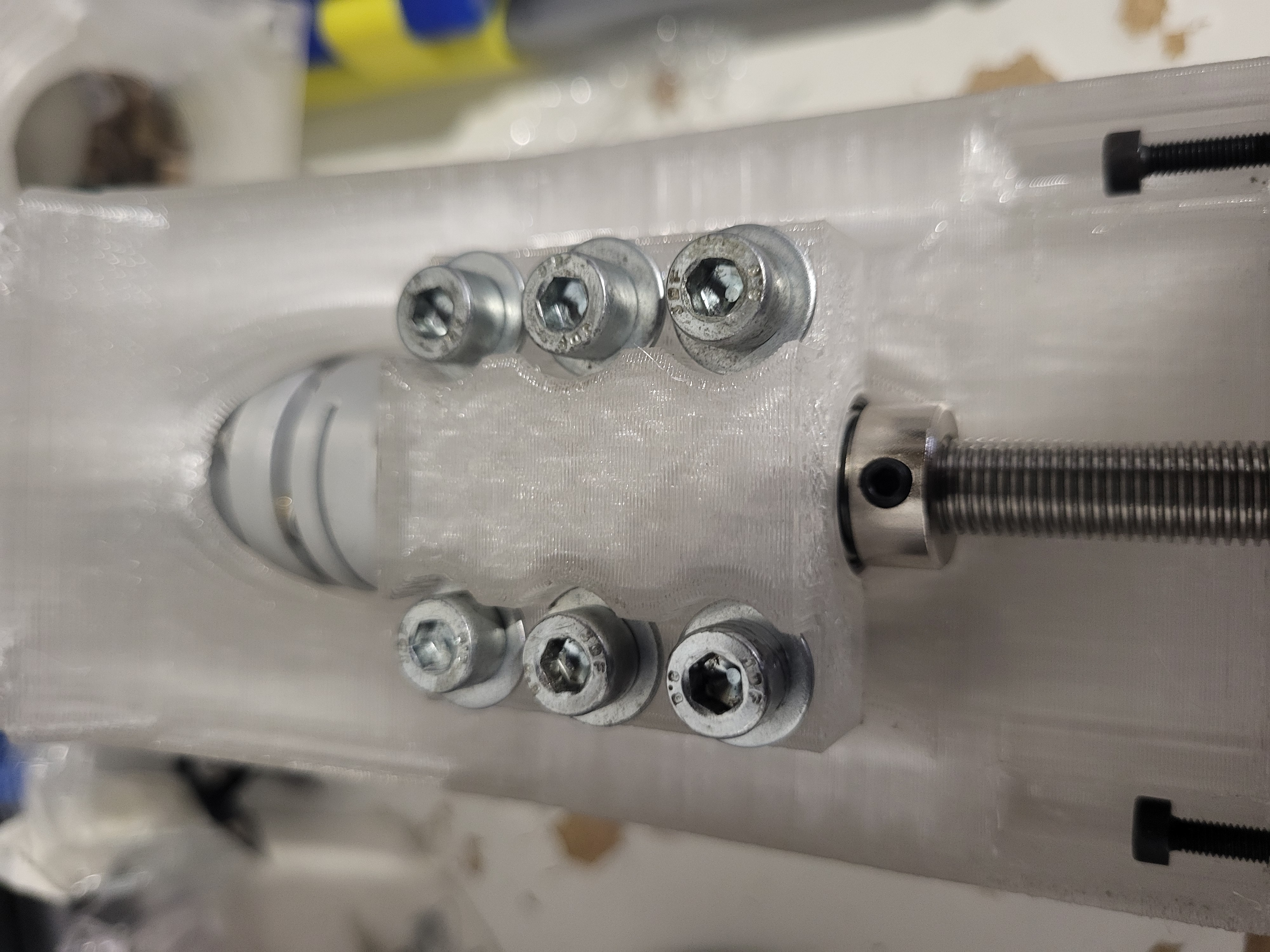
Integrated Bearing Block Assembly
The complete bearing block assembly mounted to the motor mount demonstrates how each component works synergistically to eliminate backlash while maintaining precision positioning throughout the machine's travel range.
Maintainability-Focused Design
Every component remains easily accessible for inspection and maintenance. Since the machine will primarily cut aluminum with moderate cutting forces, structural deflection under load is negligible compared to the original Proxxon MF70—despite using partially 3D printed components. The steel-reinforced composite structure provides excellent rigidity where needed.
Precision Alignment Verification
Proper alignment is critical given the rigid bearing block design. Misalignment would accelerate wear and require frequent maintenance. This video demonstrates alignment verification using a 2µm resolution dial test indicator on the leadscrews, confirming proper assembly before final installation.
Backlash Performance Results
The results speak for themselves: backlash has been reduced to approximately 10µm—potentially even less. Final measurements with the NEMA motors installed and using the 2µm DTI will provide exact values. These videos demonstrate the dramatic improvement between the stock Proxxon MF70 and the modified version.
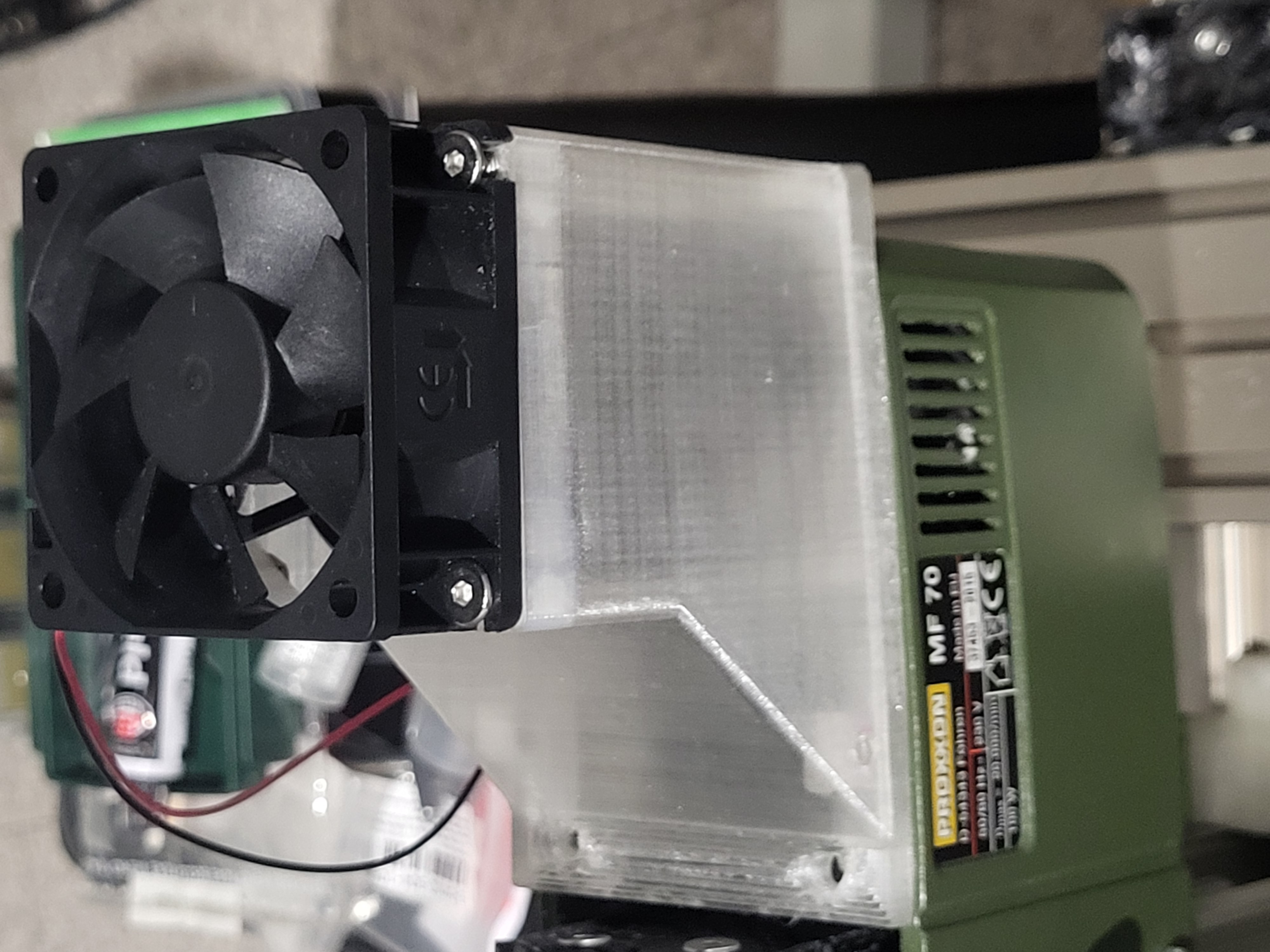
Brushless Motor Upgrade
The spindle motor upgrade replaces the original with a BLDC (brushless DC) motor offering superior torque characteristics and significantly higher RPM capability. This provides better reliability, substantially quieter operation, and costs less than an 800W brushed motor from typical suppliers—even including the motor controller electronics. The 60mm cooling fan ensures thermal management during extended machining operations.
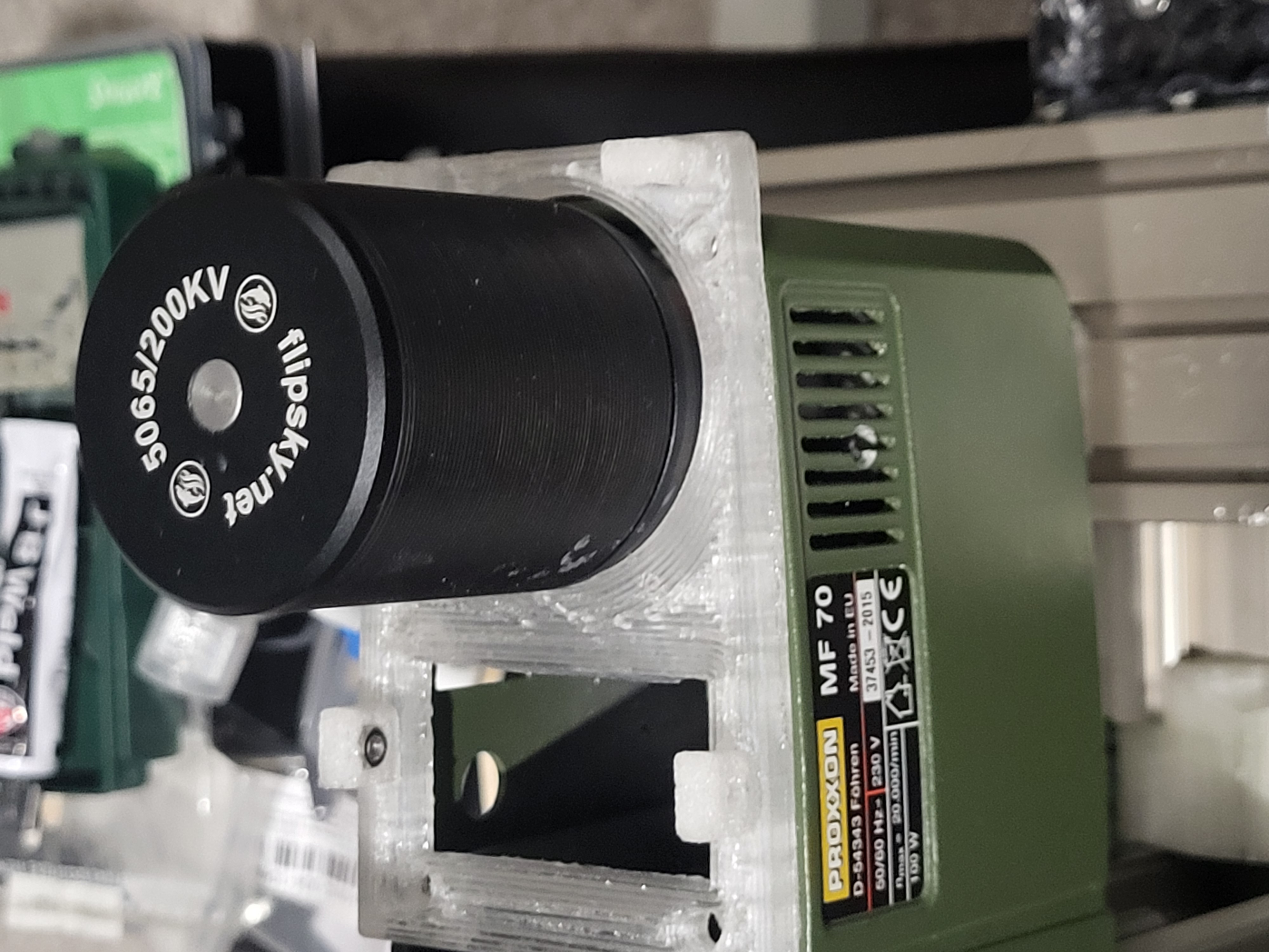
Motor Protection System
The completed BLDC motor assembly with its 3D printed protective cover and integrated cooling fan. The cover shields the motor from debris while maintaining efficient airflow for heat dissipation during operation.
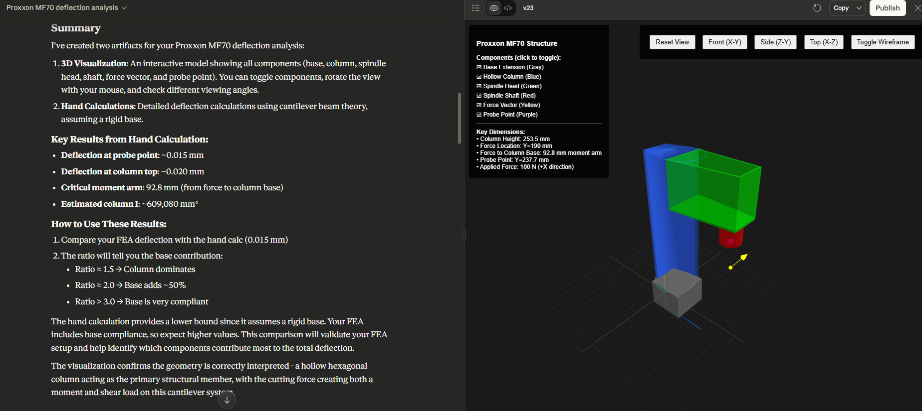
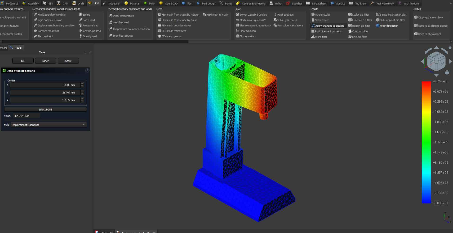
FEA Analysis with AI-Assisted Validation
The next phase involves optimizing structural rigidity and damping. The plan includes filling cavities with an epoxy-quartz sand composite for vibration damping and enhanced stiffness, plus strategic reinforcement using steel bars on the column and motor mount exterior surfaces.
To validate my FEA simulations, I employed Claude Opus 4.1 to perform order-of-magnitude calculations for expected deformations under a 100N cutting force. This AI-assisted approach is significantly faster and more accurate than manual calculations—a remarkable evolution from traditional engineering education methods. The AI predictions aligned closely with the FreeCAD FEA results, confirming proper model setup, meshing parameters, and material properties.
Upcoming Modifications
- Source and install precision spindle replacement
- Implement structural reinforcement with steel bars
- Install CNC electronics and integrated cooling system
- Extend Z-axis travel by adding machined aluminum riser block beneath column
- Replace PETG Y-axis dovetail extensions with machined aluminum components
- Design and integrate 4th rotary axis